How to Install a Ground Rod: Step-by-Step Guide
To install a ground rod, choose a code-compliant location clear of the structure, drive the rod vertically into the soil to full depth (commonly at least 8 ft / 2.4 m of contact with the earth, to reach lower-resistance moist soil), and bond the earth conductor to it with a proper ground rod clamp. If a single rod can’t reach a low enough earth resistance, add a second rod (spaced apart) or drive deeper by coupling rods. Always follow your local electrical code (NEC, IEC, or national standard) depth, spacing, and resistance targets are set by code and the earthing design.
A ground rod is only as good as its installation. Driven too shallow, spaced wrong, or bonded poorly, it won’t give the low-resistance path to earth that protects people and equipment. This step-by-step guide covers how to install a ground rod correctly and what to do when the soil fights back.
Before You Start: What a Ground Rod Does
A ground rod (earth rod) is a metal electrode driven into the soil to give fault and lightning current a safe path into the earth. The goal of installation is a low, stable earth resistance and that depends on depth (reaching moist, conductive soil), the rod (material and size), and the bond (a solid connection to the earth conductor). Get those right and the earth works; get them wrong and it’s unreliable.
(Depths, spacing, and resistance targets below are typical code/design guidance follow your local standard.)
Step 1: Choose the Location
Pick a spot that:
- Is clear of the structure’s foundation (a short distance away, per code) to avoid interference and damage.
- Reaches naturally moist soil where possible moist soil has lower resistivity and gives a better earth.
- Is accessible later for inspection and testing of the connection.
- Avoids buried services always check/locate underground utilities before driving.
Step 2: Choose the Right Rod
The rod material and size affect the earth and the rod’s life:
- Copper-bonded ground rod a steel core with a thick bonded copper layer, for high conductivity and long corrosion life, especially in aggressive soils and with copper earthing systems.
- Hot-dip galvanized ground rod the economical zinc-coated steel electrode for shorter design lives or zinc/steel systems.
Common rod sizes and lengths are set by your standard. Choose the rod by design life, soil, and the metal of your earthing system (see our copper-vs-galvanized guide). Both are part of the ground-rod range.
Step 3: Drive the Rod to Full Depth
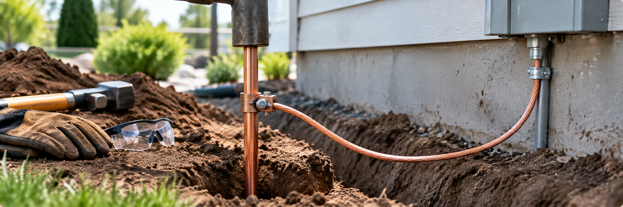
Drive the rod vertically into the soil to its full depth commonly at least 8 ft (2.4 m) of contact with the earth under codes such as the NEC, to reach the lower-resistance moist soil below the surface layers (which dry out and freeze). Use a hammer, sledgehammer, or a powered driver; a driving cap protects the rod top. A few inches may remain above grade for access to the connection.
If you hit rock or hard ground and can’t drive to full depth, codes typically allow alternatives: drive the rod at an angle (e.g. up to 45°), or lay it horizontally in a trench at the required depth. Don’t cut the rod to make it fit that defeats the purpose.
Step 4: Bond the Earth Conductor
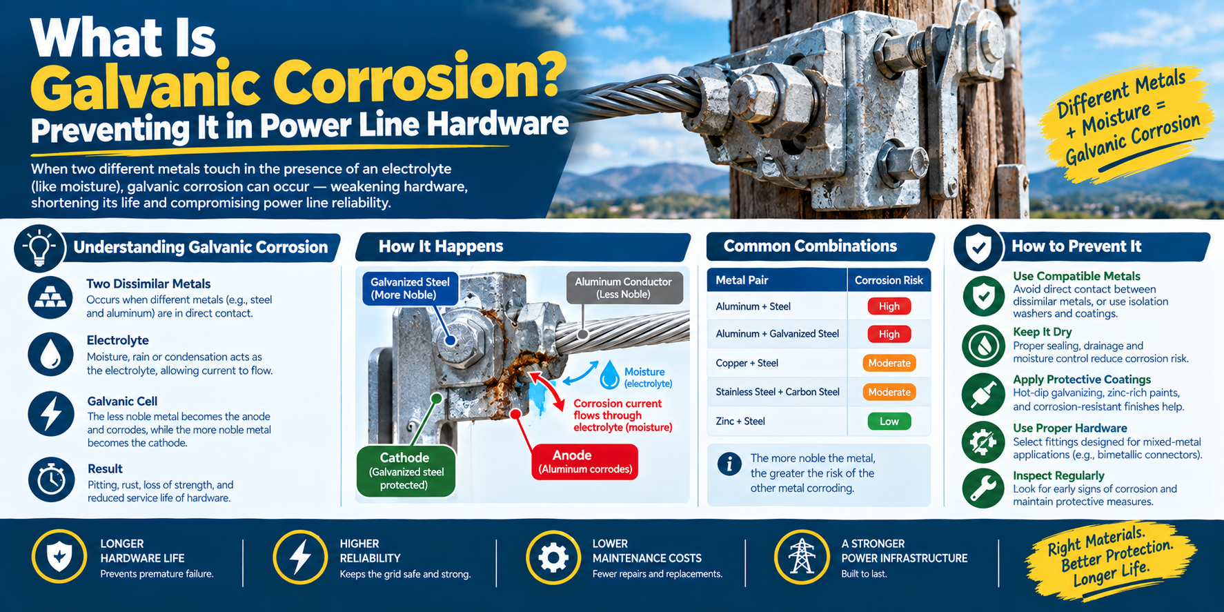
Connect the earth conductor to the rod with a proper ground rod clamp usually copper-alloy, and direct-burial rated if the connection is below grade. The clamp must grip both the rod and the conductor solidly, metal-to-metal, so current flows freely. A loose or corroded bond is a failed earth. Match the metals: a copper conductor wants a copper-alloy clamp on a copper-bonded rod mixing metals (e.g. copper on bare galvanized) causes galvanic corrosion that raises resistance over time.
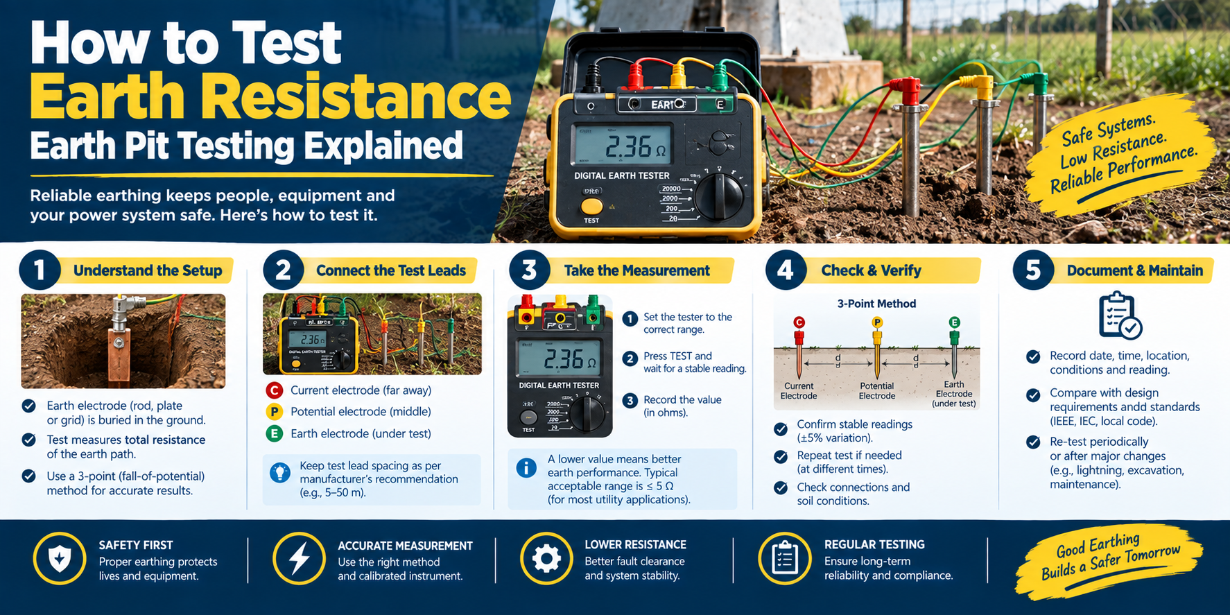
Step 5: Test the Earth Resistance
Measure the earth resistance. Codes set a target under the NEC, a single rod that doesn’t achieve 25 ohms or less requires a supplemental (second) rod. If your reading is too high:
- Add a second rod, spaced apart (commonly at least 6 ft / 1.8 m) and bonded to the first.
- Drive deeper by coupling rods (see next section).
- Improve the soil with an earth-enhancing compound where permitted.
When One Rod Isn’t Enough: Reaching Lower Resistance
In dry, rocky, or high-resistivity ground, one rod often can’t hit the target. Your options:
- Couple rods and drive deeper a ground coupling rod joins rods end-to-end so you can drive as one continuous electrode into deeper, moister, lower-resistance soil (a driving stud protects the thread while driving).
- Multiple rods several rods, spaced and bonded together as one grounding system.
Depth is the strongest lever, because resistivity usually falls with depth. Coupling makes a deep-driven earth practical without an impossibly long single rod.
How to Install a Ground Rod: FAQ
How deep should a ground rod be driven? Codes commonly require at least 8 ft (2.4 m) of the rod in contact with the earth, to reach the lower-resistance moist soil below the surface. The exact depth is set by your local code and the earthing design; deeper generally means lower resistance. If rock blocks full depth, codes allow angled or horizontal installation.
How far apart should two ground rods be? When a second rod is needed, it’s commonly spaced at least 6 ft (1.8 m) from the first and bonded to it, per codes such as the NEC. Check your local standard for the exact spacing. Adequate spacing lets each rod develop its own low-resistance zone rather than overlapping.
What clamp connects the conductor to the ground rod? A ground rod clamp usually copper-alloy and direct-burial rated for below-grade connections. It grips the rod and the earth conductor solidly, metal-to-metal. Match the clamp metal to the conductor and rod to avoid galvanic corrosion that would raise resistance over time.
What if I can’t drive the rod to full depth? If you hit rock, codes typically allow driving the rod at an angle (up to about 45°) or laying it horizontally in a trench at the required depth. Don’t cut the rod. Alternatively, use multiple rods or an earth-enhancing compound to reach the resistance target.
How do I lower ground rod resistance? Drive deeper (couple rods to reach moist soil), add supplemental rods spaced apart and bonded together, increase the rod diameter, or use an earth-enhancing compound where permitted. Depth is usually the most effective, because soil resistivity falls with depth.
Copper-bonded or galvanized ground rod for installation? Copper-bonded for high conductivity and long life, especially in aggressive soils or copper systems; galvanized for economical, shorter-life or zinc/steel systems. Match the rod to your earthing system’s metal to avoid galvanic corrosion. (See our copper-vs-galvanized guide.)
The Bottom Line
Installing a ground rod comes down to five steps: choose a good location, choose the right rod, drive it to full depth, bond the conductor with a matched clamp, and test the resistance adding rods or driving deeper if the earth resistance is too high. Follow your local code (NEC/IEC/national) for depth, spacing, and resistance targets, and match your metals to keep the earth working for decades.
DAPENG Power (DP Power Fitting) manufactures the earthing hardware for the job copper and galvanized ground rods, coupling rods for deep driving, and the rod, strand, and I-beam bonding clamps. Tell us your soil, resistance target, and earth-conductor metal, and we’ll specify a matched earthing kit.