How to Test Earth Resistance: Earth Pit Testing Explained
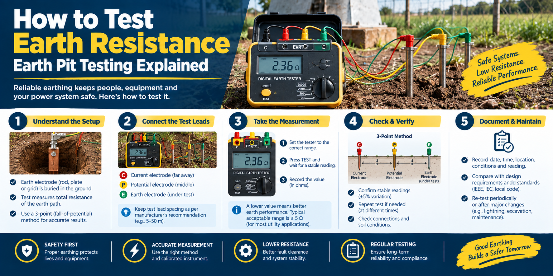
To test earth resistance, use an earth resistance tester (earth megger) with the fall-of-potential method: disconnect the earth electrode from the system, drive two temporary spikes into the ground at set distances in a line from the electrode, connect the tester’s terminals to the electrode and the two spikes, and take the reading in ohms. A low value (commonly 25 ohms or less for many installations, and lower for substations, per your standard) is good; if it’s too high, improve the earth by driving deeper, adding rods, or treating the soil. Test periodically, ideally in the dry season when resistance is highest.
Earth resistance testing confirms that your earthing system actually gives a low-resistance path to ground the whole point of earthing. An untested earth can be quietly failing. This guide explains how to test earth resistance, step by step.
Why Test Earth Resistance?
An earthing system’s job is to provide a low-resistance path to earth. But resistance can be too high from the start (poor soil, shallow electrode) or rise over time (corrosion, drying soil). If it’s too high, fault and lightning current can’t dissipate safely, and the protection fails invisibly, underground. Testing is how you confirm the earth is good, and catch problems before they matter. It’s done at commissioning and periodically thereafter.
The Fall-of-Potential Method (Most Common)
The standard method for testing an earth electrode’s resistance is the fall-of-potential (three-point) method, using an earth resistance tester (earth megger):
- Disconnect the electrode from the installation (so you measure the electrode, not the whole system).
- Drive two temporary spikes (auxiliary electrodes) into the ground in a straight line away from the electrode under test one at a middle distance (the potential spike, P) and one further out (the current spike, C), at the distances the tester specifies.
- Connect the tester: its terminals to the electrode under test (E), the potential spike (P), and the current spike (C).
- Take the reading the tester passes a current and measures the resistance, showing the earth resistance in ohms.
- Verify move the potential spike (P) a little and re-read; if the value stays roughly constant, the reading is valid (the spikes are far enough apart).
The result is your earth electrode’s resistance. Simpler two-point and clamp-on methods also exist for certain situations, but fall-of-potential is the standard for a proper electrode test.
What’s an Acceptable Value?
The acceptable earth resistance is set by your standard and installation type:
- Many general installations aim for 25 ohms or less (common code guidance); if a single rod exceeds it, a supplemental rod is added.
- Substations and critical installations require much lower values.
- Follow your standard for the target it varies by application.
A lower resistance is always better for safety. If your reading exceeds the target, improve the earth.
If the Resistance Is Too High
If the test shows too high a value:
- Drive deeper couple rods with a ground coupling rod to reach moist, low-resistivity soil.
- Add rods more ground rods, spaced apart and bonded together.
- Treat the soil charcoal/salt or an earth-enhancing compound around the electrode.
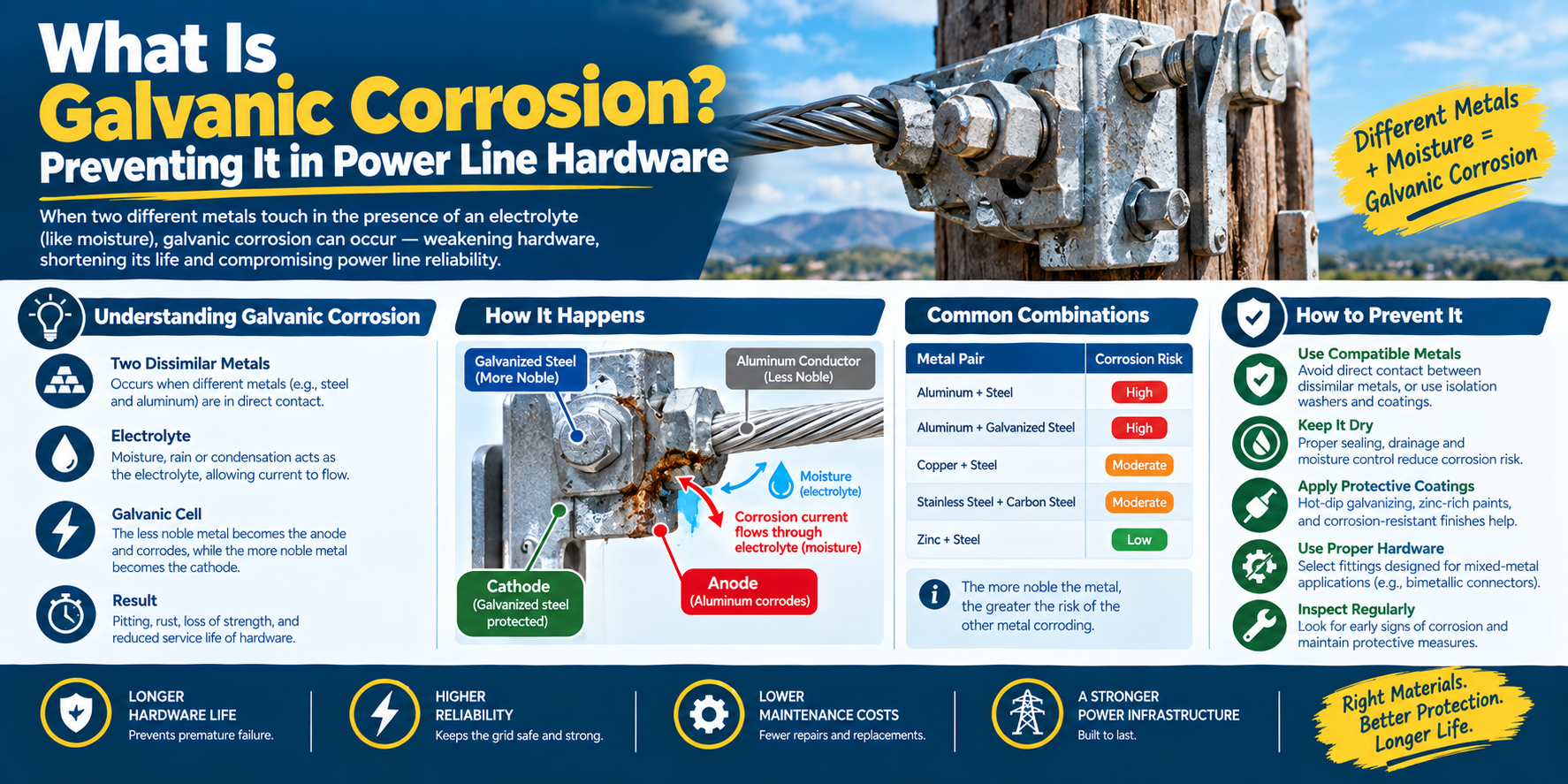
- Check the bonds a corroded or loose connection (clamp) raises the measured resistance; ensure metal-to-metal contact and matched metals.
Then re-test to confirm the improvement. (See our how-to-reduce-earth-resistance guide.)
Testing Tips
- Test in the dry season resistance is highest when the soil is driest, so a dry-season test is the worst case.
- Disconnect the electrode from the system for an accurate electrode reading.
- Keep spikes in line and far enough apart too close and the reading is invalid.
- Record and trend periodic tests show if the earth is degrading over time (often from corrosion).
- Check the bonds a good electrode with a bad clamp still tests high.
How to Test Earth Resistance: FAQ
How do you test earth resistance? Use an earth resistance tester with the fall-of-potential method: disconnect the electrode, drive two temporary spikes in a line at set distances, connect the tester to the electrode and the two spikes, and read the resistance in ohms. Move the middle spike and re-read to verify the value is valid.
What is the fall-of-potential method? It’s the standard three-point method for testing an earth electrode’s resistance. An earth tester passes current between the electrode and a far current spike, and measures the voltage at a middle potential spike, calculating the resistance. Moving the potential spike and getting a stable reading confirms the spikes are far enough apart.
What is an acceptable earth resistance value? It depends on your standard and installation. Many general installations aim for 25 ohms or less (common code guidance), while substations and critical sites need much lower values. Lower is always better; follow your standard’s target for the application.
When should earth resistance be tested? At commissioning and periodically thereafter ideally in the dry season, when soil resistance is highest (the worst case). Periodic testing catches a rising resistance from corrosion or drying soil before the protection is compromised.
Why is my earth resistance too high? Usually because of poor (dry, rocky, high-resistivity) soil, a too-shallow or too-small electrode, or a corroded/loose bond. Drive deeper (couple rods), add spaced rods, treat the soil, and check the connections. A corroded clamp can raise the reading even with a good electrode.
Do I need to disconnect the electrode to test it? For an accurate electrode reading, yes disconnect the electrode from the installation so you measure the electrode’s resistance to earth, not the whole system’s parallel paths. Some clamp-on methods measure without disconnecting, but fall-of-potential needs the electrode isolated.
The Bottom Line
Testing earth resistance with the fall-of-potential method and an earth tester confirms your earthing gives a low-resistance path to ground. Aim for your standard’s target (commonly 25 ohms or less generally, lower for substations), test in the dry season, disconnect the electrode for accuracy, and if the value is too high, drive deeper, add rods, treat the soil, or fix the bonds then re-test.
DAPENG Power (DP Power Fitting) manufactures the earthing hardware to reach and hold a low resistance copper and galvanized ground rods, coupling rods for deep driving, and matched rod, strand, and I-beam bonding clamps. Tell us your soil and resistance target, and we’ll specify the electrode system.