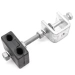
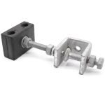
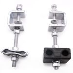
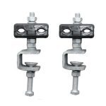
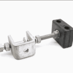
Description
What Protects the Last Thirty Metres of a Hundred-Kilometre Fibre Route?
An OPGW or ADSS route is engineered span by span, tensions calculated, dampers placed, clearances checked, for tens or hundreds of kilometres. Then, at the splice tower, the cable does something no span ever asked of it: it turns and runs straight down a steel structure, past bracing, bolt heads, and edges, exposed to every gust, all the way to the joint box.
Leave that descent unmanaged, and the wind manages it for you: the cable slaps against the lattice in every storm, saws gently against edges in every breeze, and hangs its own weight plus wind load on whatever grips it at the top. The fibres that crossed a province without incident get destroyed in the last thirty metres, at the one location on the route with the most steel to hit.
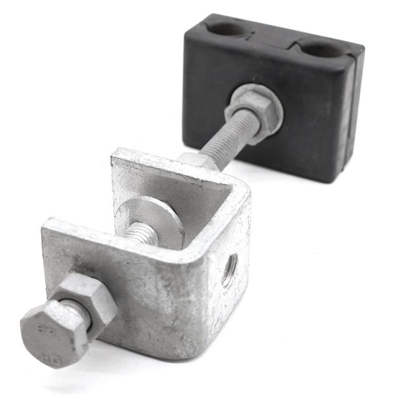
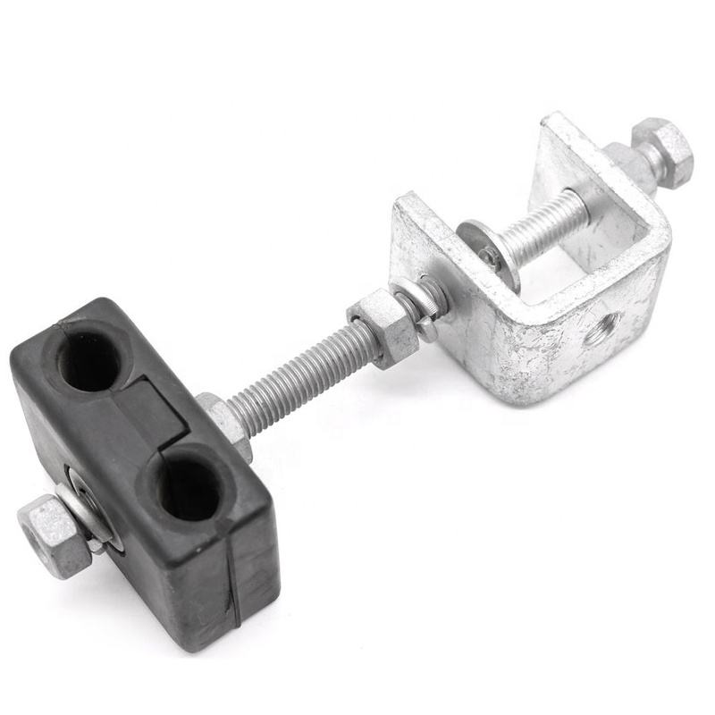
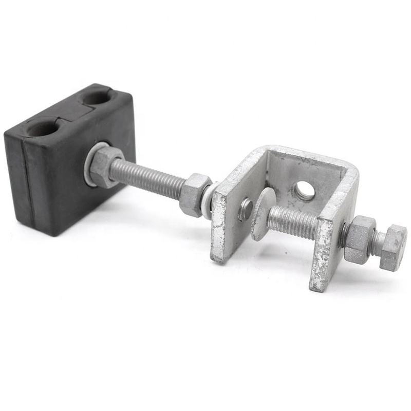
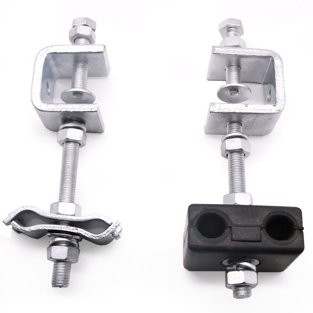
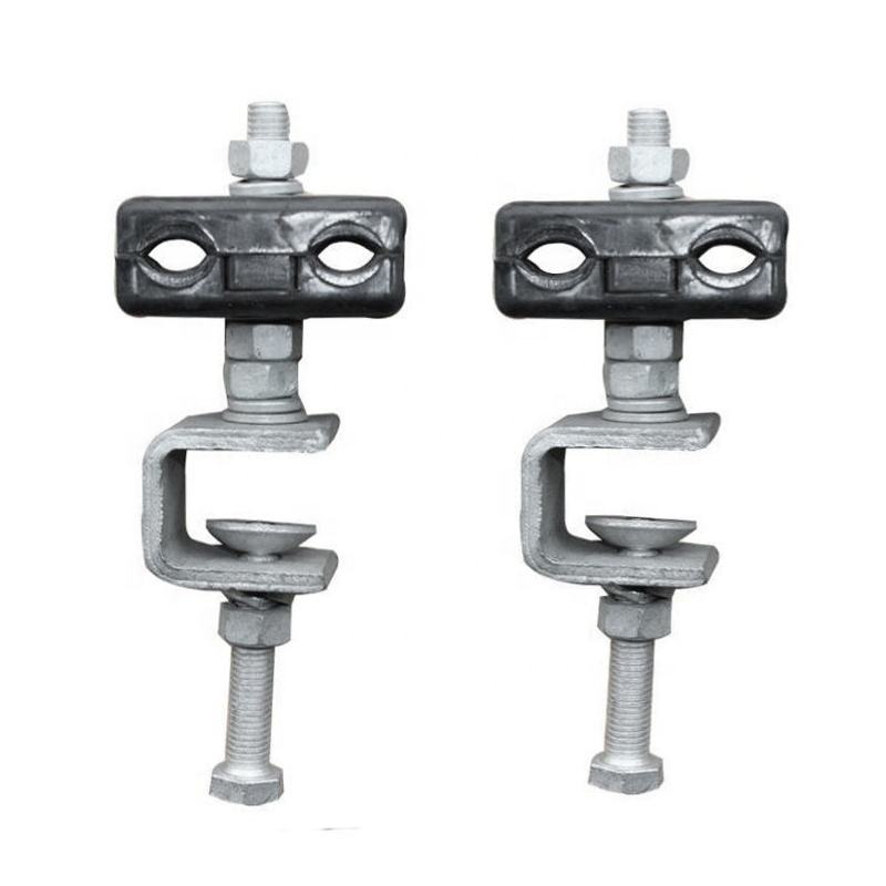
The down lead clamp is the fitting that closes this gap: a rubber-cushioned clamp, fixed to the structure at regular intervals, that pins the downlead firmly, gently, and permanently along its descent. If your route BOM is asking how many downlead clamps per tower, which fixing type, and what spacing, this page answers all three.
How a Down Lead Clamp Works
Each clamp does three jobs at once:
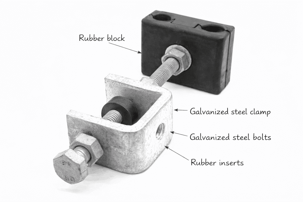
- Grips without grinding. The cable sits in an elastomer-lined saddle; the clamp closes on the rubber, and the rubber holds the cable. Metal never touches the sheath or strands, so thirty years of micro-movement wears nothing that matters.
- Breaks the span of “free” cable. Fixed at intervals of roughly 1.5–2 meters down the structure (per project spec), the clamps divide the descent into short, stiff sections that wind cannot excite. No free length, no slap, no fatigue.
- Respects the bend radius. At the transitions, over the tower arm at the top, into the junction box or closure at the bottom, clamp placement holds the cable’s curve above its minimum bend radius, the invisible line between a working fiber and an attenuation fault.
Why Buyers Choose DAPENG Down Lead Clamps
- Two fixing families, matched to your structures. Tower patterns bolt directly to lattice members, hot-dip galvanized bodies drilled for standard member sizes. Pole patterns fix with stainless steel banding straps and buckles around concrete, steel, or wooden poles, no drilling, any diameter. Tell us the structure schedule; the carton mix matches it.
- Sized to the cable, stated per model. Saddle and insert diameters matched to your OPGW or ADSS datasheet, because a loose clamp is a rattle and a tight one is a crush point, and both are avoidable with one datasheet at RFQ. (Slip-strength and clamping ratings)
- Materials for a no-return-visit service life. Hot-dip galvanized steel (ISO 1461 / ASTM A153 class) or aluminum alloy bodies; UV-stable, weather-rated elastomer inserts that stay resilient through decades of thermal cycling, at the top of a tower nobody climbs twice for a clamp.
- Counted by the route, not the piece. Downlead quantities are simple arithmetic, descent height ÷ spacing + transition clamps, × structures, and we do it with you: send tower heights and splice-point counts, receive a per-structure kit list.
- The whole splice point from one factory. Downleads ship with the ADSS/OPGW metal junction box, the fiber optic closure inside it, the banding that mounts it all, and the tension and suspension hardware of the spans above, one matched kit per structure, one accountable supplier.
Use-Case Deep Dive
How many down lead clamps does each tower need, and at what spacing?
Divide the cable’s descent length by the specified interval, commonly 1.5 to 2 meters, per your project standard, then add clamps at every direction change (the arm crossing at the top, the approach to the joint box at the bottom) where the bend must be held on radius. A typical transmission-tower splice point lands in the range of a dozen to two dozen clamps depending on tower height and routing; a pole splice point needs proportionally fewer. Send the structure drawings and splice-point schedule with your RFQ and the quotation returns as a per-structure count, arithmetic we’d rather do twice on paper than have a crew discover short at height.
Which fixing type do I need, bolted or banded?
By structure, not preference. Lattice towers: bolted patterns, fastened to member steel with standard hardware, rigid, permanent, galvanized end to end. Poles (concrete, steel, wood): banded patterns using stainless banding straps and buckles, fitting any diameter without drilling, which matters on concrete poles where drilling is prohibited and wooden poles where it invites rot. Mixed routes simply order both patterns, marked by structure type on the cartons. One route, one RFQ, two patterns, zero site improvisation.
Do ADSS and OPGW use the same down lead clamps?
The role is identical; the variant differs with the cable. OPGW downleads run metallic cable on grounded structures, galvanized clamp bodies are standard, and the downlead path coordinates with the earthing arrangement at the tower. ADSS downleads carry a dielectric sheath that must not be nicked, insert profiles and clamping pressures suit the softer jacket. Specify the cable datasheet per route section and each section’s clamps arrive matched; where one tower carries both (common at transition structures), the kit is marked accordingly.
Specifications and What They Mean for You
| Specification | What we do | What it means for the buyer |
|---|---|---|
| Grip system | Elastomer-lined saddle; metal never touches cable | Decades of micro-movement wear the rubber’s job, not the fiber’s |
| Fixing | Bolted (tower) and banded (pole) patterns | Matches your structure schedule; no drilling where drilling is banned |
| Materials | HDG steel (ISO 1461/ASTM A153 class) / aluminum alloy; UV-stable inserts | Install once at height; never climb back for the clamp |
| Cable matching | Saddle sizes per OPGW/ADSS datasheet | Neither rattle nor crush, confirmed at RFQ in writing |
| Spacing practice | Supports 1.5–2 m interval installation + transition points | The descent becomes short stiff sections wind can’t excite |
| Ratings | Clamping/slip values per model | Real metric numbers on the datasheet, tested per batch |
Straight Answers to Common Buyer Concerns
“It’s the cheapest item on the tower. Why give it a second thought?” Because of where it fails. A slipped span fitting shows up in an inspection; a chafed downlead shows up as an attenuation fault that takes the route’s availability with it, and the repair is a tower climb, a splice crew, and an outage window at the exact point where the network’s most valuable asset meets the most steel. The clamp costs least of anything on the structure; its failure costs most per gram. That asymmetry is the whole specification argument.
“How do we verify quality on hardware this simple?” The same regime as the rest of the route kit: batch clamping and material verification with reports supplied, galvanizing coating class checkable with a gauge on arrival, elastomer samples available for your own UV/aging assessment, and third-party pre-shipment inspection (SGS/BV or your agency) welcome. Simple hardware, checkable claims.
“Our route has legacy structures with odd member sizes, will the bolted pattern fit?” Send the member dimensions or a photo with a tape measure in frame. Bolt patterns are drilled to order for non-standard members as routine OEM work, and where a member defeats bolting, the banded pattern fits anything with a circumference. Between the two families, we have not yet met a structure we couldn’t clamp to, and if yours is the first, you’ll get an engineered answer, not a shrug.
Complete the Splice Point
- ADSS/OPGW metal junction boxes – where the downlead is going
- Fiber optic closures – the splice the whole descent protects
- Stainless steel banding straps and buckles – the pole-fixing system
- Preformed tension clamps and Stockbridge dampers – the span hardware above the descent
- Browse all ADSS/OPGW fittings for the complete route
Get a Per-Structure Kit Quote Within 24 Hours
Send the structure schedule, cable datasheets, and splice-point locations, or simply the route drawings. Our engineers return the clamp counts per structure, the fixing pattern per structure type, and a factory-direct quotation for the complete splice-point kits, typically within one working day.
After You Order
Count-and-pattern confirmation before production, batch test reports with shipment, cartons kitted and marked per structure so the climb takes everything it needs in one bag, and an engineering contact who answers while the crew is still on the tower, because the descent gets clamped today, not after next week’s email.