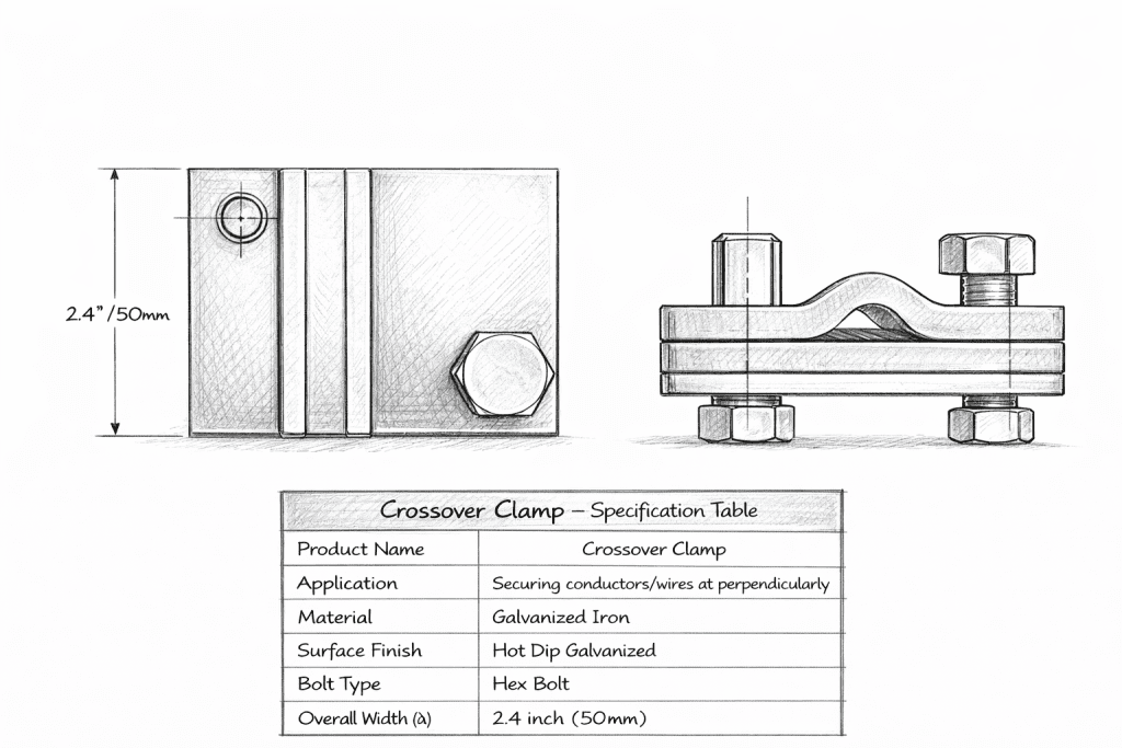
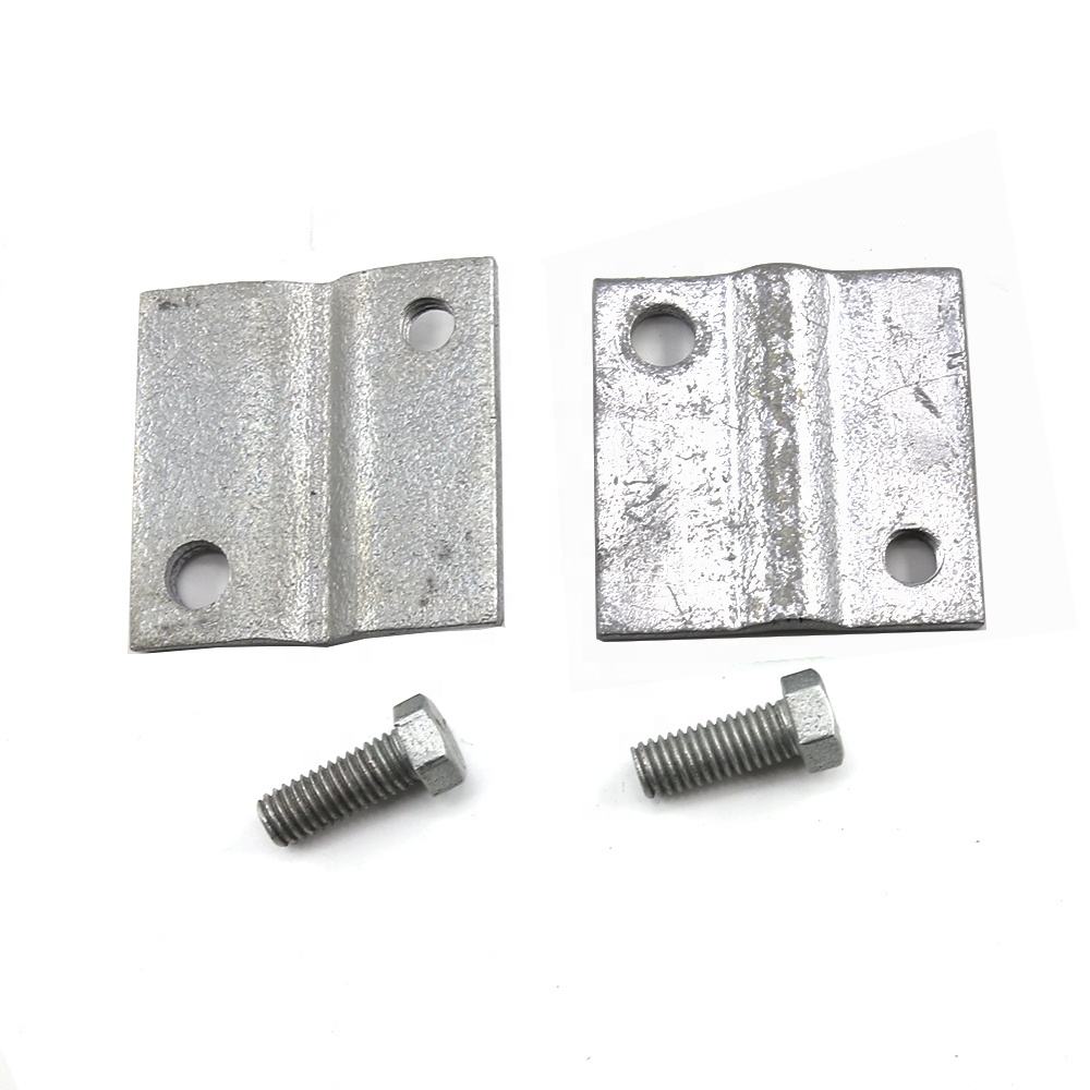
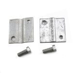
Description
What Keeps Two Conductors From Clashing Where Lines Cross?
Overhead networks are not tidy grids; they cross. A distribution line passes under a transmission line; a service spur crosses a feeder; two circuits share a corridor and run close for a span. At every one of those points, two conductors that must never touch are held apart by nothing but air and geometry.
Air and geometry are not always enough. Wind pushes conductors toward each other. Galloping, the slow, large oscillation driven by ice and wind, can swing a conductor a meter or more. And two lines rarely sag identically: different tensions, spans, and temperatures mean the gap between them changes with the weather. Let that gap close, and the result is a clash: a flashover, a burnt conductor, a tripped circuit, and in the worst case a conductor down across the line beneath it.
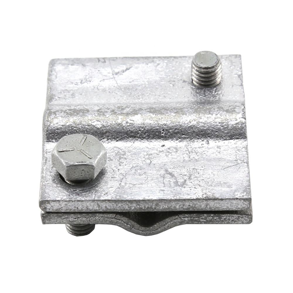
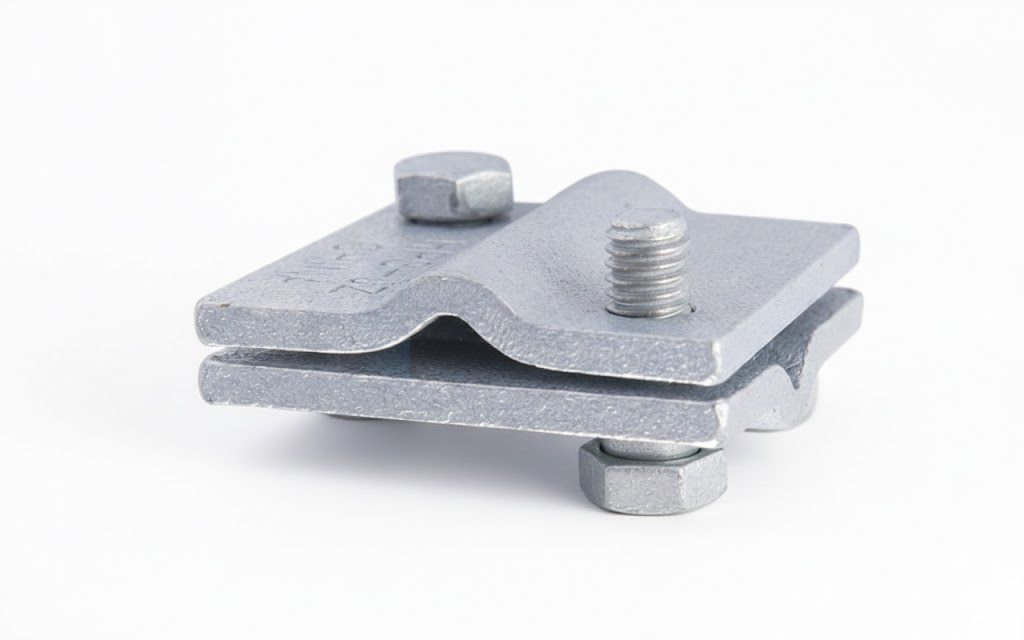
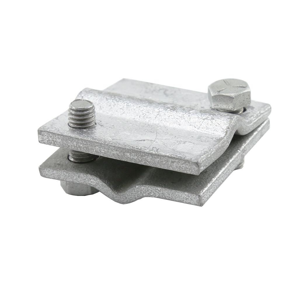
The crossover clamp is the fitting that removes the uncertainty. It fixes the separation between conductors at the crossing or close-approach point, so the gap the design specified is the gap that stays, through wind, galloping, and differential sag.
What a Crossover Clamp Does
A crossover clamp holds two conductors at a set distance from one another at the point where they cross or run close. Rather than trusting span geometry to keep the gap, the clamp makes the gap a fixed, mechanical fact:
- It maintains separation at the crossing, so wind and galloping cannot drive the conductors together.
- It manages differential movement between two lines that sag and sway independently, holding the relationship between them steady.
- It protects both circuits, a clash damages the conductor above as surely as the one below, and trips both.
The clamp is a spacing fitting: its job is geometric, keeping conductors apart. That places it in the same family as the spacer dampers and bolted cable spacers that hold sub-conductor geometry within a bundle, different application, same underlying principle: where a gap matters, don’t leave it to chance.
Why Crossings Are a Specific Hazard Worth Engineering For
Most of a line’s length is a simple span between two supports, and the clearances there are set once by the tower geometry. A crossing is different, it’s the one place where two independent mechanical systems interact, and their interaction changes with conditions no single line’s design fully controls:
- Differential sag: The upper and lower lines expand and sag at different rates with temperature and load. On a hot, heavily-loaded afternoon the gap can be at its smallest exactly when the line most needs it.
- Independent galloping: Under icing, each line can gallop on its own cycle; two conductors swinging out of phase can close a generous static gap in a single oscillation.
- Wind from any quarter: A crosswind that pushes both conductors the same way still changes their relative position if their spans and tensions differ.
A crossover clamp turns that uncertainty into a fixed dimension. It is cheap insurance against a failure mode, the crossing clash, that takes out two circuits at once and can drop a conductor onto the public.
Why Buyers Choose DAPENG Crossover Clamps
- Separation held as a mechanical fact: The clamp fixes the gap the crossing design specified, so weather cannot renegotiate it.
- Conductor-matched grips: Groove profiles sized to your conductors, cushioned and specified so the clamp holds without fretting the conductor over years of movement.
- Corrosion-protected for the long term: Materials and finish specified for permanent outdoor service at a point the maintenance cycle rarely reaches.
- Built to the crossing geometry: Separation distance and clamp configuration to your crossing design, the required gap is a design output, and the clamp is made to hold it.
- From the factory that makes the rest of the span: Crossover clamps quoted alongside the suspension clamps, spacer dampers, vibration dampers and connection hardware of the same line, matched to one conductor schedule.
Use-Case Deep Dive
Where exactly is a crossover clamp installed?
At the point of closest approach between the two conductors, where a crossing line passes over or under another, or where two circuits run parallel and close enough that clash is credible under wind or galloping. The clamp is positioned to hold the two conductors at the separation the crossing design requires, taking account of the worst-case conditions (maximum differential sag, galloping envelope) rather than the still-air geometry. Send the crossing detail, the two conductors, their relationship, and the required separation, and we confirm the clamp and its placement.
Does a crossover clamp handle two different conductor sizes?
Frequently, yes a crossing often involves conductors of different sizes (a transmission conductor above, a distribution conductor below, for instance). The clamp’s two grips are specified independently, each matched to its conductor, so neither is pinched or left loose. Give us both conductor sizes and constructions with the RFQ and each grip is sized to its own conductor.
How is this different from a spacer or a spacer damper?
Same family, different job. Spacer dampers and bolted cable spacers hold the sub-conductors of one bundle at their designed spacing along a span. A crossover clamp holds two conductors of different circuits apart at a crossing or close approach. Both are spacing fittings; the crossover clamp is the one you reach for when the risk is two separate lines clashing rather than a bundle collapsing. If your project has both bundled spans and crossings, both fittings appear on the BOM, send the line design and we quote them together.
Specifications and What They Mean for You
| Specification | What we supply | What it means for the buyer |
|---|---|---|
| Function | Fixed conductor separation at crossings/close approaches | The design gap holds through wind, galloping and differential sag |
| Conductor grips | Two grips, each sized to its conductor | Handles different sizes on the two circuits; neither pinched nor loose |
| Separation | Built to the crossing design | The clamp holds the gap the clearance study required |
| Materials | Corrosion-protected for permanent service | Decades at a point maintenance rarely reaches |
| Grip construction | Cushioned, profiled, torque-defined | Holds without fretting the conductor over years of movement |
| Verification | Batch testing, reports supplied | Mechanical performance on tested figures |
Straight Answers to Common Buyer Concerns
“Is a crossover clamp really necessary, or is span clearance enough?” Span clearance is set for still-air, average conditions; a crossover clamp exists for the conditions that clearance doesn’t cover, differential sag on a hot loaded day, independent galloping under ice, wind on two lines with different tensions. Where a crossing’s worst-case geometry brings the conductors within clashing distance, the clamp is the difference between a designed margin and a hoped-for one. Whether your specific crossing needs one is a clearance question we’re glad to review from the crossing detail.
“How do we know the grips won’t damage the conductors over time?” The same way as any spacing fitting: grooves machined to your stated conductor diameters, cushioned interfaces, and defined installation torque, all verifiable before purchase through material certificates, sample inspection, and batch test reports. Fretting is a known mechanism with known countermeasures, and the countermeasures are checkable.
“Can you match an unusual crossing geometry or conductor pair?” Send the crossing detail, both conductors, their sizes and constructions, and the required separation. Non-standard geometries are routine OEM work; the clamp is built to your dimension and confirmed by drawing before production. A crossing designed to a national standard deserves a clamp that fits it, not one that nearly does.
Complete the Line
- Spacer dampers and bolted cable spacers – spacing within bundled conductors
- Suspension clamps and armor grip suspension – tangent support
- Stockbridge and spiral vibration dampers – vibration control
- Parallel groove clamps and hot line clamps – conductor connections and jumpers
- Browse all overhead line fittings and pole line hardware
Get a Crossing-Matched Quote Within 24 Hours
Send the crossing detail, both conductors and their sizes, the required separation, and the crossing geometry, or the line drawing showing where circuits cross or run close. Our engineers confirm the clamp, size each grip to its conductor, and return a factory-direct quotation, typically within one working day.
After You Order
Confirmation drawings before production, batch test reports and material certificates with shipment, clamps kitted to the crossings they serve, and an engineering contact who answers while the crew is still on site, because crossing hardware is installed at specific, surveyed points, and a question there shouldn’t hold up the span.