
Description
The Angle-Steel Arm That Carries the Conductors Out
Every pole has to hold its conductors out and apart, clear of the pole and each other, at the spacing the design requires. The electrical cross arm does it: an angle-section steel arm, bolted to the pole, that carries the insulators and, through them, the conductors. It’s the working arm of the structure, strong, straight, and galvanized to last as long as the pole.
Angle steel is the right section for the job: an L-shaped profile gives strength and stiffness in the directions the arm is loaded (the conductor’s weight down, the tension and wind sideways), efficiently and economically. Our electrical cross arms come in a range of angle sections sized to the load, with end holes for the insulators and a central attachment for the string. This page covers them: the sections we make, how to pick one, and how the arm completes into a braced assembly.
Electrical Cross Arm Sections
(EC series, hot-dip galvanized, angle sections in mm. From the Dapeng catalog; sizes customizable.)
| Type | Angle section (mm) |
|---|---|
| EC01 | 40 × 40 × 4 |
| EC02 | 50 × 50 × 5 |
| EC03 | 60 × 60 × 6 |
Reading the sections: the angle size sets the arm’s strength a larger, thicker angle (60×60×6) carries more load over a longer arm than a lighter one (40×40×4). Match the section to your conductors’ weight, the arm length, and the loads at your structure. Sections and lengths outside this range are made to your drawing.
How the Arm Is Built: Ends, Centre, and Bail
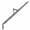
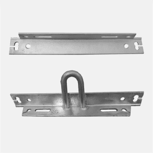
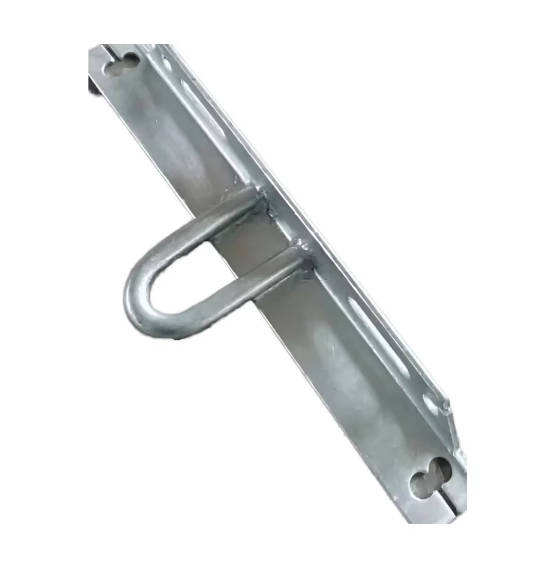
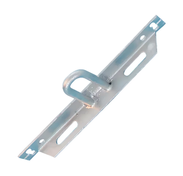
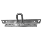
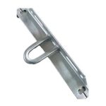
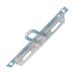
The image shows the working features of the electrical cross arm:
- End mounting holes at each end of the arm, for the insulator pins or brackets that carry the outer conductors.
- Central mounting where the arm bolts to the pole (with a double arming bolt or through the mounting hardware).
- Central U-bolt / shackle bail (on the relevant version) an attachment point at the center or a position along the arm where a suspension string or fitting hangs from the arm, for the conductor supported below the arm rather than on top.
So one electrical cross arm can carry conductors on it (on pins/insulators at the end holes) and below it (on a string from the central bail) the configuration depends on your structure.
Why Buyers Choose DAPENG Electrical Cross Arms
- Angle steel sized to the load: EC sections from 40×40 to 60×60 (or to your drawing), matched to your conductors, span, and loads the right strength, not over- or under-built.
- Drilled and bailed to fit: End holes for the insulators, central mounting, and the U-bolt bail where your string hangs so the arm arrives ready to assemble, not needing field work.
- Hot-dip galvanized to ISO 1461: The same coating class as the bolts, braces, and fittings it carries, so the whole assembly ages together.
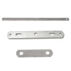
- Braced into a rigid assembly: Supplied with the flat crossarm braces that hold the arm square a complete arm, not just the angle.
- The whole structure from one source: Electrical cross arms with the insulators, pins, braces, mounting hardware, and bolts matched and kitted per structure.
Use-Case Deep Dive
How do I choose the section (EC01, EC02, EC03)?
By the load and the arm length. The section (angle size) carries the arm’s load: the conductors’ weight, wind and ice, and any unbalanced tension. A short arm with light conductors uses the lighter section (EC01/40×40×4); a longer arm or heavier load steps up to EC02 (50×50×5) or EC03 (60×60×6). The length is set by the conductor spacing your design and voltage need. Send the conductor spacing, the conductors, and the structure type, and we confirm the section and length or build to your standard drawing.
What’s the central bail for?
For suspending the conductor below the arm. Where a conductor hangs from a string rather than sitting on a pin on top of the arm, the string attaches to the arm’s central U-bolt/shackle bail the arm carries the string, and the string carries the conductor through its suspension clamp. This lets one arm support conductors both on top (pins) and below (string), in the configuration your structure needs. Tell us your conductor arrangement and we’ll supply the arm to match.
How does the arm mount and stay square?
The arm bolts to the pole at its center (through a double arming bolt or mounting hardware), and the flat crossarm braces triangulate it to the pole so it holds square and doesn’t rotate or sag under load. The arm and its braces are a structural assembly we supply them together, drilled to fit, so the arm mounts rigid and level.
Specifications and What They Mean for You
| Specification | What we supply | What it means for the buyer |
|---|---|---|
| Section | EC 40×40 to 60×60 angle steel | Strength matched to your span and load |
| Length | To your conductor spacing | The geometry your design needs |
| End holes | For insulators/brackets | Carries the outer conductors |
| Central bail | U-bolt for string suspension | Supports a conductor below the arm |
| Coating | HDG to ISO 1461 class | Ages with the arm’s hardware |
| Bracing | Flat braces supplied | The arm holds square under load |
Straight Answers to Common Buyer Concerns
“Which section do we need EC01, 02, or 03?” By the load and arm length: EC01 (40×40×4) for short arms and light conductors, stepping up through EC02 (50×50×5) to EC03 (60×60×6) for longer arms or heavier loads. The section carries the conductor weight, wind, and tension, so it’s matched to your structure send the conductors, the spacing, and the loads and we’ll confirm the section, or build to your standard drawing.
“Can you drill and bail it to our arrangement?” Yes send your conductor arrangement (on-arm and/or below-arm) and the geometry, and the arm arrives with the end holes, central mounting, and the U-bolt bail where your string hangs, galvanized and ready to assemble. No field drilling.
“Can you supply the arm complete with braces, insulators, and bolts?” Yes the electrical cross arm, its flat braces, the insulators and pins, the mounting hardware, and the bolts come matched and kitted per structure one order, one delivery, everything fits.
Complete the Structure
- Steel cross arms the crossarm category hub and material choice
- Power pole cross arms and V-type cross arms the sibling crossarm types
- Flat crossarm braces the braces that hold the arm square
- Insulator pins, pin insulators, insulators what the arm carries
- D brackets, pole bands, double arming bolts, square head machine bolts mounting hardware
- Browse all pole line hardware and overhead line fittings
Get a Structure-Matched Quote Within 24 Hours
Send your conductor spacing, the conductors and loads, the arrangement (on-arm and/or below-arm), the structure type, and quantities or the crossarm standard drawing. Our engineers confirm the EC section, length, holes, and bail, and quote the arm complete with braces, insulators, and mounting hardware, typically within one working day.
After You Order
Section, length, and drilling confirmation before production, galvanizing certificates with shipment, arms drilled, bailed, and braced to fit and kitted with their insulators and mounting hardware per structure, and an engineering contact who answers precisely because the crossarm sets the conductor geometry, and getting the section and drilling right is what keeps the line where the design put it.