Power Line Clearances: Safe Distances Explained
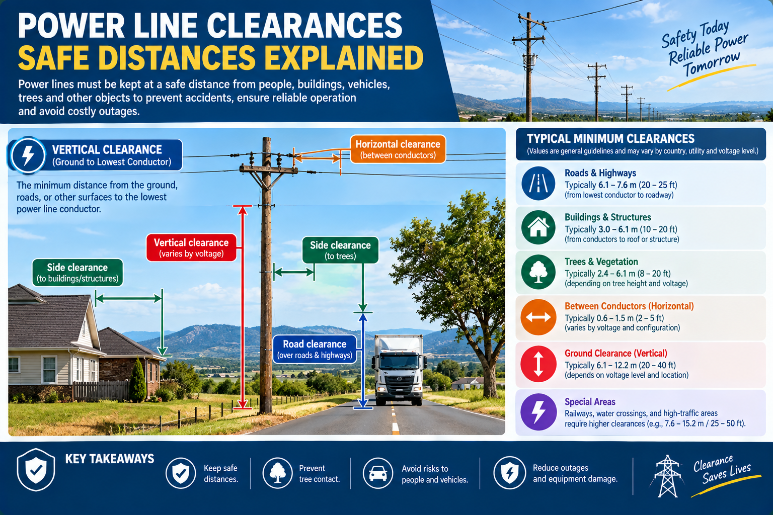
Power line clearances are the minimum safe distances that must be maintained between energized conductors and the ground, objects, buildings, other lines, and each other. They exist so that electricity can’t arc across or be reached, keeping people and property safe. The main types are ground clearance (conductor to ground), vertical and horizontal clearance (to buildings, roads, and other lines), and phase-to-phase and phase-to-earth clearance (between conductors and to the structure). The exact distances depend on the voltage, the conditions (sag, wind), and your local code or standard; higher voltages need larger clearances.
Clearances are fundamental to power line safety: too little, and electricity can arc or be touched; too much, and the line is uneconomical. This guide explains the types of power line clearances and what sets them. Always follow your local code and standard for the actual required distances.
Why Clearances Matter
An energized conductor is dangerous in two ways: electricity can arc across a gap to a nearby object (the higher the voltage, the larger the gap it can jump), and a person or object can touch or come near the conductor. Clearances keep enough distance that neither happens. They’re a core safety requirement set by electrical codes and standards, and they drive much of a line’s design the pole height, the conductor spacing, and the structures.
Important: the specific clearance distances vary by voltage, country, and standard, and this guide explains the concept, not the numbers. Always use your local code for the actual required distances.
Types of Power Line Clearances
Ground clearance
Ground clearance is the minimum height of the conductor above the ground (or above roads, railways, water). It must be enough that people, vehicles, and equipment below can’t reach or arc to the conductor accounting for the conductor’s maximum sag (hot day, high load see our sag-and-tension guide). Ground clearance is higher over roads and railways than over open ground, and scales with voltage.
Vertical and horizontal clearance to objects
Vertical and horizontal clearances are the minimum distances from the conductor to buildings, structures, trees, and other objects both beside the line (horizontal) and above/below (vertical). These keep the line clear of anything that could be touched from a building or that the conductor could swing into in wind.
Clearance between lines
Where lines cross or run parallel, there are minimum clearances between the two lines (and between a line and communication cables), so they can’t contact or arc to each other, including under wind sway and different sag.
Phase-to-phase and phase-to-earth clearance
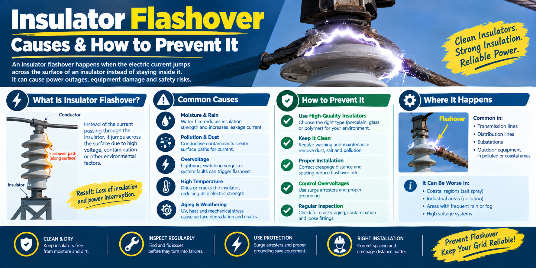
On the structure itself, there are minimum clearances between the conductors (phase-to-phase) and between each conductor and the earthed structure (phase-to-earth). These set the conductor spacing on the crossarm and the insulator length the insulator provides the phase-to-earth clearance along its surface and through the air. (See our insulator-specifications guide.)
What Sets the Required Clearance
The required clearance depends on several factors:
- Voltage higher voltage can arc across a larger gap, so needs more clearance. This is the biggest factor.
- Sag the conductor sags more on hot days at high load, reducing ground clearance; the clearance must hold at maximum sag. (See our sag-and-tension guide.)
- Wind sway wind swings the conductor sideways, reducing horizontal clearance; this is accounted for.
- The situation more clearance over roads, railways, and buildings than over open ground.
- The standard your national code sets the specific minimums.
So clearance isn’t a single number it’s a set of minimums for each situation, driven mainly by voltage, and confirmed against the standard.
How Clearances Drive the Hardware
Clearances determine much of the line hardware:
- Phase spacing the phase-to-phase clearance sets how far apart the conductors sit on the crossarm, which sizes the crossarm.
- Insulator length the phase-to-earth clearance (and creepage for pollution) sets the insulator size or the number of discs in a string.
- Pole height ground clearance (plus sag) sets how tall the pole must be.
- Conductor tension affects sag, and therefore ground clearance (see our sag-and-tension guide).
So getting the clearances right flows through to the crossarm, insulators, and structure all sized to maintain the safe distances.
Power Line Clearances: FAQ
What are power line clearances? Power line clearances are the minimum safe distances between energized conductors and the ground, objects, buildings, other lines, and each other. They prevent electricity from arcing across or being reached, keeping people and property safe. The distances depend on voltage, conditions, and the applicable code.
What is the safe distance from a power line? It depends on the voltage and your local code higher voltages require larger safe distances because electricity can arc across a bigger gap. There’s no single number; always follow your national standard for the required clearance, and treat any line as dangerous. For work near lines, consult the specific code and the utility.
What is ground clearance for a power line? Ground clearance is the minimum height of the conductor above the ground (or roads, railways, water), set so people and vehicles below can’t reach or arc to it. It must hold at the conductor’s maximum sag (hot, high-load conditions), is higher over roads and railways, and increases with voltage.
Why do higher voltage lines need more clearance? Because a higher voltage can arc across a larger air gap, so more distance is needed to prevent a flashover to the ground, objects, or other conductors. Clearance requirements scale up with voltage a key reason high-voltage transmission lines are strung much higher and with wider spacing than distribution lines.
What affects power line clearance? Voltage (the biggest factor), conductor sag (worse on hot days at high load, reducing ground clearance), wind sway (reducing horizontal clearance), the situation (more over roads and buildings), and the applicable standard. Clearances are confirmed at the worst-case conditions.
How do clearances affect line design? Clearances set the phase spacing (and so the crossarm size), the insulator length or number of discs (phase-to-earth clearance), and the pole height (ground clearance plus sag). So the required safe distances flow through to the crossarm, insulators, and structure design.
The Bottom Line
Power line clearances are the minimum safe distances between conductors and the ground, objects, other lines, and each other set mainly by voltage, and confirmed at worst-case sag and wind. They drive the phase spacing, insulator size, and pole height. The specific distances come from your local code and standard always follow it; this guide explains the concept, not the numbers.
DAPENG Power (DP Power Fitting) manufactures the hardware that maintains your clearances crossarms sized to the phase spacing, insulators and strings for the phase-to-earth clearance, and the conductor fittings that hold the designed sag and tension. Tell us your voltage and spacing requirements, and we’ll specify the hardware.