Description
Where Does a Fiber Splice Live on a Transmission Tower?
A hundred kilometers of OPGW is a sealed, armored, engineered thing until the splice point. There, the cable comes down the structure, the fibers are opened, and the most delicate object on the entire route ends up sitting at a height a person can reach, in the weather, for thirty years.
That location needs three things a bare splice cannot provide on its own: mechanical protection from impact and interference, somewhere to keep the slack that every future repair will need, and a fixed, earthed mounting to the structure.
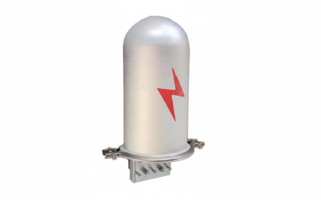
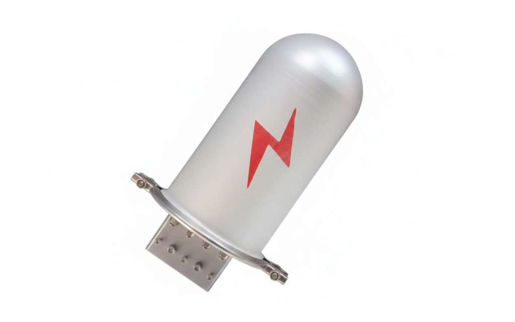
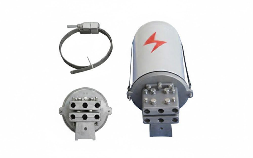
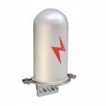
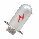
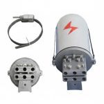
The ADSS/OPGW metal junction box provides all three. If your route design is asking what goes at the splice tower and what it needs to contain, this page covers the box, what belongs inside it, and how it mounts.
Junction Box or Fiber Closure? The Distinction That Prevents Double-Ordering
This confuses buyers constantly, so here it is plainly:
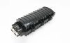
A fiber optic closure is the sealed inner enclosure that organizes and waterproofs the splices themselves, trays, gel or heat-shrink entry seals, IP68 protection. A metal junction box is the outer enclosure that mounts to the structure and protects the closure inside it from impact, weather, UV, and interference, while storing the cable’s slack loops. Many utility standards specify both together; some specify an integrated box that performs the closure’s sealing function itself.
- Closure inside a box, the common utility arrangement, and the configuration this page describes. The closure does the sealing and splice organization; the box does the mounting, armoring, slack storage and security.
- Integrated metal box, the box itself seals and organizes. Fewer parts, but the closure’s re-entry and sealing performance must live in the box’s own design.
Order to your standard, not by assumption, and if your specification names one and describes the other, send it to us and we’ll flag the mismatch before it becomes a delivery of half a splice point.
Why Buyers Choose DAPENG Junction Boxes
- Built for the tower, not the equipment room. Robust metal construction, aluminum alloy or coated steel per specification, engineered for decades of UV, rain, thermal cycling, and the vibration a structure transmits.
- Lockable, and specified for real conditions. On routes where accessible hardware attracts attention, a lockable metal enclosure is not a convenience feature: it removes the casual opportunity that a visible closure invites. It deters opportunistic vandalism and interference, no enclosure is theft-proof, and any supplier promising that is selling a claim. What a well-made box buys you is time, difficulty, and a route that isn’t the easiest target on the line.
- Slack storage where the re-entry will happen. Interior provision for the cable loops a splice crew needs to lower the closure and re-terminate, because a splice point without stored slack can be repaired exactly once, and then only by cutting into the route.
- Earthing provision for metallic routes. OPGW is a current-carrying, earthed cable on an earthed structure; the box carries grounding provision so the installation bonds correctly rather than improvising with whatever the crew has in the truck. Pair with the grounding range , strand ground clamps and ground rod clamps , from the same order.
- The complete splice point from one factory. Box, closure, down lead clamps routing the cable to it, banding straps and buckles mounting it, and the tension, suspension and damping hardware of the spans above, kitted per structure, one container, one set of documents.
Use-Case Deep Dive
How is a junction box mounted on a transmission tower versus a pole?
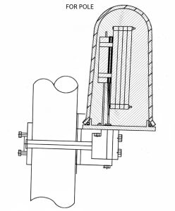
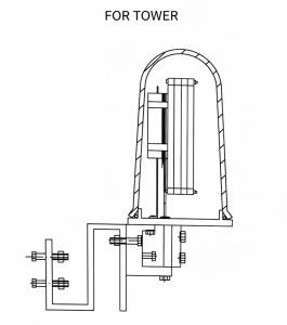
Lattice towers: bolted to member steel using the box’s fixing provisions, at the height your standard specifies, high enough to be out of casual reach, low enough that a splice crew can work it safely. Concrete, steel or timber poles: mounted with stainless steel banding straps and buckles, which fit any diameter without drilling, mandatory on concrete, and sensible on timber where every hole is a moisture path.
The cable reaches the box down the structure, pinned at roughly 1.5-2 meter intervals by down lead clamps, with the final clamps positioned to hold the entry curve above the cable’s minimum bend radius. Send the structure schedule and the quotation returns as a per-structure kit, box, mounting, downlead count, and closure, rather than a list of parts you have to reconcile yourself.
Why does the box need to store slack cable?
Because every splice point is opened again eventually, a fiber cut nearby, a network extension, a capacity upgrade, a fault investigation. Re-entry means lowering the closure to a working position, and that requires stored cable. A splice point built without slack forces a crew to cut fresh cable into the route and add another joint (and another loss budget) every time.
Stored loops must be held on a radius above the cable’s minimum, secured against wind, and protected from abrasion, which is precisely what the box’s interior provision does. It is the least glamorous specification on the page and the one your maintenance team will thank you for in year seven.
Does an ADSS route need the same box as an OPGW route?
The mechanical role is identical; two details differ. OPGW is metallic and lives on earthed structures, the earthing provision matters and the downlead path coordinates with the tower’s bonding arrangement. ADSS is fully dielectric, the box protects the splice mechanically, and the hardware around it (anchoring clamps, our PAL series covers 10-150 mm² with 5-18 mm messenger diameters at 10-15 kN, the PA series 4-15 mm cable at 2.5-10 kN, plus aluminum supports and spiral dampers) is chosen for the dielectric sheath. Routes carrying both, common at transition structures, take a mixed kit marked by structure. For the full comparison, see our engineering guide: ADSS vs OPGW: Which Fiber Optic Cable Is Right for Your Project?
Specifications and What They Mean for You
| Specification | What we supply | What it means for the buyer |
|---|---|---|
| Construction | Metal body | Decades of UV, rain and vibration at height, without degradation |
| Sealing / ingress | Weather kept out of the splice environment | |
| Access | Lockable closure | Deters opportunistic interference; authorized access only |
| Interior | Closure mounting + slack loop storage | Every future re-entry is possible without cutting the route |
| Mounting | Tower bolt fixings and pole banding patterns | Fits your structures without drilling where drilling is banned |
| Earthing | Grounding provision | Correct bonding on OPGW routes, not site improvisation |
| Cable entries | Sized per cable datasheet at RFQ | Seals and clamps match the cable you actually run |
On the markers: every one is deliberate. We publish IP ratings, capacities and material grades only from factory test data, never indicative figures borrowed from another supplier’s catalogue. Send the drawings and this becomes the most complete page on the topic in your export markets.
Straight Answers to Common Buyer Concerns
“Do we actually need a metal box, or is the closure enough?” It depends on where the splice lives and who can reach it. On a remote transmission tower with the joint well above ground, some standards accept a closure alone. On accessible structures, in populated corridors, or in regions where exposed hardware attracts interference, the metal box is what keeps the splice point boring, and boring is exactly what you want at the one location where a hundred kilometers of route becomes reachable by hand. We will tell you honestly which your situation calls for; we sell both.
“How do we verify quality on an enclosure we won’t open for ten years?” Component by component before it ships: coating class checkable with a gauge on arrival, ingress-protection test documentation supplied with the batch, hinge, lock and gasket samples available for your own assessment, and third-party pre-shipment inspection (SGS/BV or your nominated agency) welcome at the factory. The parts that fail first on a cheap enclosure, the hinge, the gasket, the lock are the cheapest ones to inspect early.
“Our utility has its own junction box drawing. Can you build to it?” Yes, and that is the bulk of our export work. Dimensions, fixing centers, entry positions, lock type, marking and packing list, manufactured to your document with confirmation drawings issued before production starts. A national standard is a specification to build to, not an obstacle.
Complete the Splice Point
- Fiber optic closures – the sealed enclosure that goes inside
- Down lead clamps – routing the cable down the structure to the box
- Stainless steel banding straps and buckles – pole mounting without drilling
- Preformed tension clamps, suspension clamps, Stockbridge and spiral dampers – the spans above
- Anchoring clamps, aluminum supports and armor grip suspension – ADSS route hardware
- Browse all ADSS/OPGW fittings and overhead line fittings
Get a Splice-Point Kit Quote Within 24 Hours
Send your cable datasheets, structure schedule, splice-point locations, and your utility’s box specification if you have one. Our engineers confirm the configuration, size the entries and slack capacity to your cable, and return a factory-direct quotation for the complete splice-point kits, typically within one working day.
After You Order
Confirmation drawings before production, test documentation and coating certificates with shipment, kits packed and marked per structure so one climb carries everything that splice point needs, and an engineering contact who answers while the crew is still on the tower, because splice points are commissioned in daylight, not in email threads.