


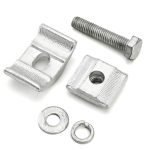
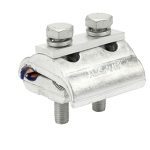
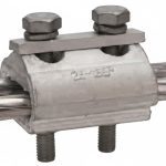
Description
How Do You Tap One Conductor Off Another, Especially When One Is Copper, and One Is Aluminium?
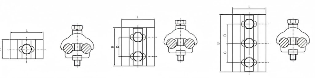
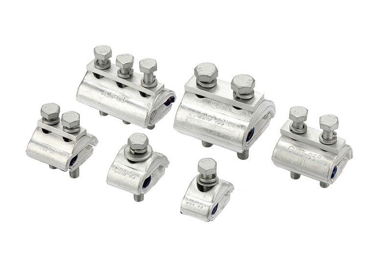
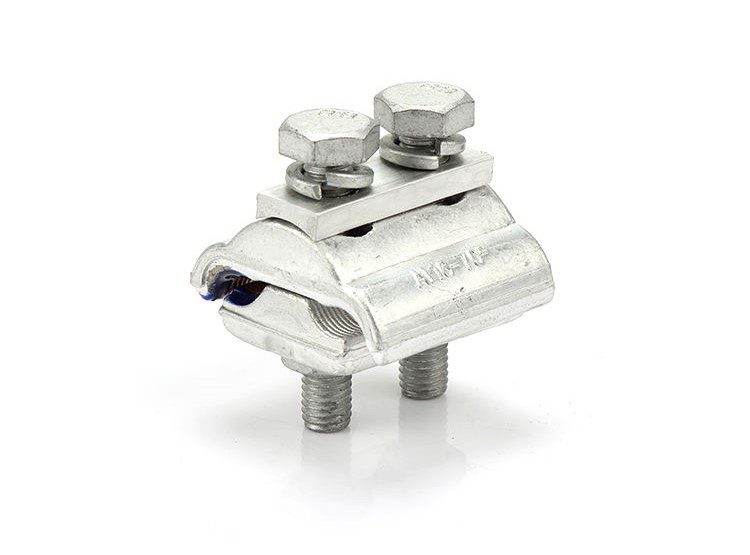
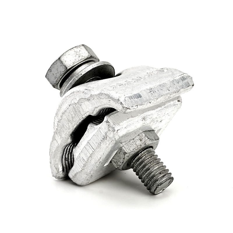
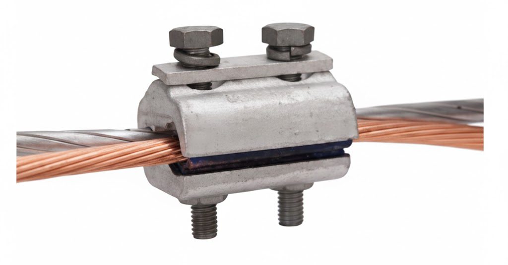
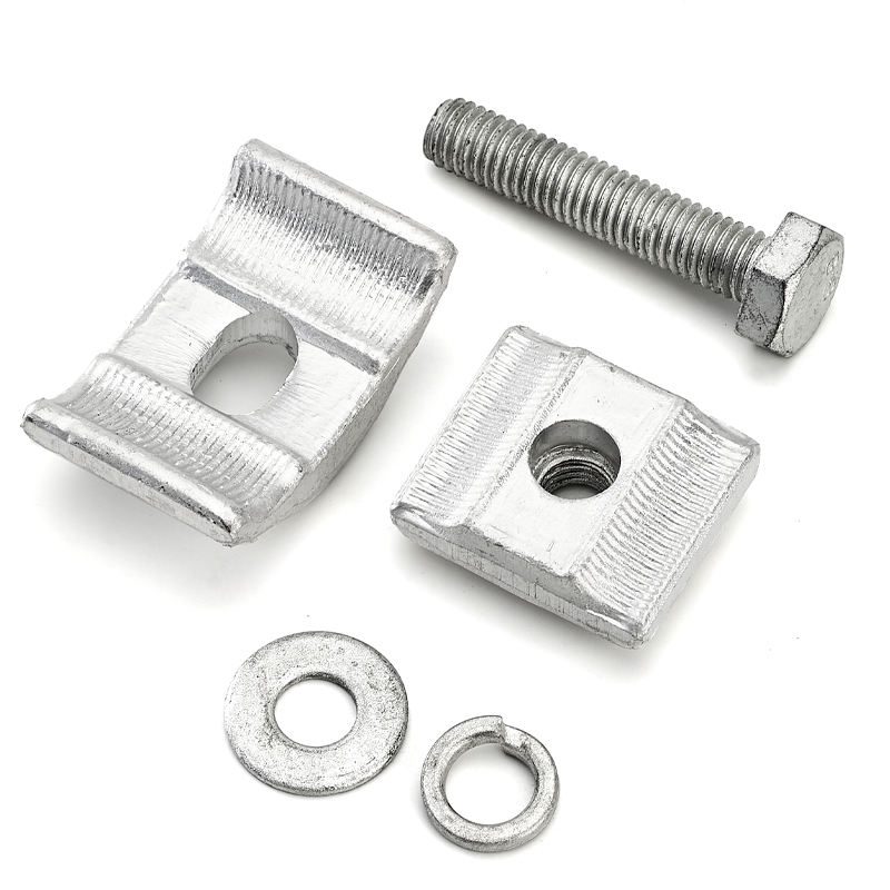
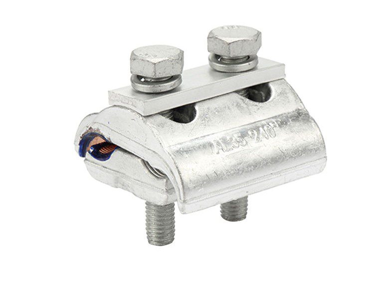
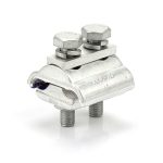
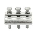
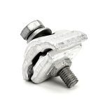
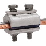
Distribution networks are built from taps and joins: a service connection off a main, a branch off a feeder, a jumper across a pole. The parallel groove clamp, the PG clamp, is the workhorse that makes them, seating two conductors side by side in parallel grooves and bolting them into firm electrical and mechanical contact.
Simple enough on a like-for-like joint. But a great many real connections are not like-for-like: a copper tap off an aluminium main, or aluminium onto copper at a transition. Bolt those two metals together in a plain clamp, in the open air, and you have built a galvanic cell. The same dissimilar-metal corrosion eats a mismatched earthing system, now sitting in your live connection, heating and degrading until the joint fails.
The answer is the bimetallic CU/AL parallel groove clamp, engineered specifically so copper and aluminium can meet without corroding. This page covers both the standard and bimetallic ranges, and just as importantly, how to make the joint last once you’ve chosen the right clamp.
The CU/AL Clamp and Why Dissimilar Metals Need One
When copper and aluminium touch in the presence of moisture, they form a galvanic couple: aluminium is anodic, corrodes preferentially, and the joint’s resistance climbs. Rising resistance means heat; heat accelerates corrosion; and the connection walks itself toward failure, a process invisible from the ground until a thermal-imaging survey or an outage reveals it.
A CU/AL parallel groove clamp breaks that cycle by keeping the two metals from forming a direct wet junction, typically through a bimetallic construction where the copper conductor seats against a copper or bimetal surface, and the aluminum against aluminum, with the transition made inside the clamp’s engineered interface rather than at a bare bolted contact.
The principle is the same one that governs ground rod selection: match the metals, or engineer the transition, never just bolt copper to aluminum and hope. Get it right and the joint outlives the survey cycle. Get it wrong and it becomes the hot spot on next year’s thermal scan.
Selection Tables
CU/AL Bimetallic – Aluminium Run, Copper Tap
| Aluminium run (mm²) | Aluminium run O.D. (mm) | Copper tap (mm²) | Copper tap O.D. (mm) | Bolts |
|---|---|---|---|---|
| 16–70 | 5.1–11.7 | 2.5–10 | 1.8–4.1 | 1 × M8 |
| 16–70 | 5.1–11.7 | 6–50 | 2.7–9.0 | 1 × M8 |
| 16–70 | 5.1–11.7 | 6–50 | 2.7–9.0 | 2 × M8 |
| 25–150 | 6.3–15.7 | 10–95 | 4.1–12.5 | 2 × M8 |
| 35–300 | 7.5–22.5 | 35–240 | 7.5–20.3 | 3 × M8 |
Aluminium (AL) – Aluminium Run
| Aluminium run (mm²) | O.D. (mm) | Bolts |
|---|---|---|
| 16–150 | 5.1–15.7 | 1 × M10 |
| 16–150 | 5.1–15.7 | 2 × M10 |
| 25–185 | 6.0–19 | 3 × M10 |
| 95–240 | 7.5–22.5 | 3 × M10 |
(All figures from the Dapeng catalog. Sizes outside these ranges are manufactured to your conductor schedule.)
How to Read the Tables – Bolt Count Is a Selection, Not a Detail
Two conductors and their sizes get you to the candidate rows; bolt count decides among them.
- More bolts = more contact force and more contact length = higher current capacity and a more secure mechanical joint. The heaviest conductors in each range use 3-bolt clamps for exactly this reason.
- Where a range appears with both 1-bolt and 2-bolt options at the same conductor sizes, the choice follows the current and mechanical duty of the specific connection, a lightly-loaded service tap versus a feeder branch carrying real current.
- Match the tap side too: On the CU/AL range, the copper tap has its own range per row; a clamp sized for the aluminum run but wrong for the copper tap is only half-specified.
Give us both conductor sizes and the connection’s duty, and the quotation returns the right clamp and bolt configuration rather than the nearest row.
Why Buyers Choose DAPENG Parallel Groove Clamps
- Bimetallic where copper meets aluminum: The CU/AL range is built to make dissimilar-metal joints that survive, not joints that become next year’s hot spot.
- Aluminum alloy bodies for the run: Corrosion-resistant, conductive, and dimensionally stable through thermal cycling, grooves profiled to seat the conductor over length rather than pinch it at a point.
- Bolts and hardware specified to hold torque: The joint’s electrical performance lives on its contact pressure; fasteners and any locking provision are specified so the torque you set on installation day is the torque the joint still has in year fifteen.
- Ranges published, not hidden: The tables above are our actual range, specify from this page, confirm at RFQ.
- The connection kit from one factory: PG clamps ship with the hot line clamps, insulation piercing connectors and the crossover clamps of the same network, matched to your conductor schedule, kitted per structure.
Use-Case Deep Dive
Parallel groove clamp or insulation piercing connector, which should I use?
The deciding factor is whether the conductor is bare or insulated.
Parallel groove clamp for bare conductors. You seat the conductors in the grooves, bolt to torque, and then insulate the finished joint (tape, cover, or boot) because the connection itself is exposed metal. The right tool on bare distribution and jumper work.
Insulation piercing connector , for insulated ABC networks. Its teeth pierce the insulation to make the connection, the body seals it, and no stripping or re-insulating is needed, often on a live line.
The wrong pairing is expensive: a PG clamp on an insulated network means stripping and re-insulating every joint by hand; an IPC on a bare network has nothing to seal against. Tell us the network type and we route you to the correct connector, we make both, so the advice has no thumb on the scale.
Does the joint really need special preparation on aluminium?
Yes, and skipping it is the most common cause of PG-clamp joints that fail early on aluminium conductors. Aluminium grows a hard, insulating oxide layer the instant it meets air. A clamp bolted over unprepared aluminium clamps onto oxide, not metal: high resistance, heat, failure. Best practice is to wire-brush the aluminium contact area and apply an oxide-inhibiting joint compound immediately before clamping, so the bolt pressure breaks through to clean metal and the compound keeps air out. On CU/AL joints this discipline matters even more. It costs a minute per joint and it is the difference between a connection that lasts decades and one that shows up on a thermal survey.
Can I use a PG clamp for guy strand or earthing connections?
Careful here, and this is where the catalog’s shared “PG” abbreviation misleads. The electrical PG clamp on this page is a conductor connector. For guy strand, the mechanical clamp on our guy clamp page is the correct product. For earthing connections to strand or structure, see strand ground clamps and the grounding range. Using an electrical connector for a mechanical strand job, or vice versa, is a specification error worth avoiding; send the application and we’ll confirm the right product.
Specifications and What They Mean for You
| Specification | What we supply | What it means for the buyer |
|---|---|---|
| Types | CU/AL bimetallic and AL-only | Copper-to-aluminum joints that survive; aluminum joins that hold |
| Conductor ranges | AL run 16–300 mm²; Cu tap 2.5-240 mm² | Published above, specify from the page |
| Bolts | 1, 2 or 3 × M8 (CU/AL) or M10 (AL) | Contact force and current capacity matched to duty |
| Body | Aluminium alloy; bimetal interface on CU/AL | Corrosion-resistant; dissimilar metals kept apart |
| Fasteners | Torque-holding, with locking provision | The joint keeps the contact pressure it was set with |
| Verification | Batch testing, reports supplied | Electrical and mechanical performance on tested figures |
Straight Answers to Common Buyer Concerns
“How do we know the CU/AL clamp actually prevents galvanic corrosion?” Ask us to state the construction, bimetal insert, plated seat, or transition interface, on the quotation, and verify it on a sample: the copper and aluminium contact zones are physically distinguishable, and material certificates confirm the metals. A supplier who can’t or won’t describe how their CU/AL clamp separates the metals is selling you a label, not a bimetallic clamp.
“These are cheap, high-volume items. Why does the source matter?” Because a failed connector is never priced at the connector: it’s a hot spot, a thermal-survey callout, and eventually an outage on the feeder it taps. The reliability lives in three things a photo can’t show, correct bimetallic construction, torque-holding fasteners, and grooves that seat the conductor properly, all verifiable through batch test reports, material certificates, and samples before a programmer order.
“Can you match our conductor schedule, including odd legacy sizes?” Send the schedule, run and tap cross-sections, and whether each conductor is copper or aluminium. Matching PG clamps to a real network’s mix of conductors is routine, and where a size falls between standard rows we tool to it. Mismatched connectors caught at RFQ cost nothing; caught on the thermal survey, they cost a truck roll.
Complete the Connection
- Insulation piercing connectors – for insulated ABC networks, no stripping
- Hot line clamps – connections made and broken with live-line tools
- Crossover clamps – managing conductor crossings and jumpers
- Guy clamps – the mechanical strand clamp (not an electrical connector)
- Strand ground clamps and the grounding range – earthing connections
- Browse all overhead line fittings and pole line hardware
Get a Conductor-Matched Quote Within 24 Hours
Send your conductor schedule, run and tap sizes, copper or aluminium, and the connection duty, or the network standard you build to. Our engineers confirm the clamp type, bolt configuration and (for CU/AL) the bimetallic construction, then return a factory-direct quotation, typically within one working day.
After You Order
Confirmation of type and construction before production, batch test reports and material certificates with shipment, clamps kitted per your connection schedule, and an engineering contact who answers while the crew is still on the pole, because distribution connections are made by the hundred, and a connector question shouldn’t cost an afternoon.